$0.00
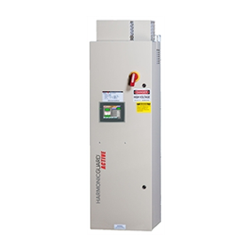
The HGA active harmonic filter actively monitors the load current, reacting to changes in load almost instantaneously, while returning true power factor to near unity.
- Haz clic para compartir en Facebook (Se abre en una ventana nueva)
- Haz clic para compartir en Twitter (Se abre en una ventana nueva)
- Haz clic para compartir en Pinterest (Se abre en una ventana nueva)
- Haz clic para compartir en Tumblr (Se abre en una ventana nueva)
- Haz clic para compartir en Google+ (Se abre en una ventana nueva)
HGA-HarmonicGuard Activo

The HGA active harmonic filter actively monitors the load current, reacting to changes in load almost instantaneously, while returning true power factor to near unity:
- Virtual real time correction of the non-linear current
- Synchronization of the current and voltage waveforms
- Always attempting to achieve unity power
- Never allowing for leading power factor
Actively Limits Harmonic Distortion
- TDD reduction to 5% or better at Full Load
- Meets IEEE-519 2014
- Improves true power factor – improves energy efficiency
- System-applied – MCC & Switchboard
- Touchscreen display
- UL 508 Certified. No SCCR required by UL Standards for the filter.
- Communication options include Modbus RTU over RS485, EtherNet/IP, Modbus TCP/IP, and DeviceNet
Fits is Narrow Spots
In a tight spot? The HGA configuration minimizes the space required for harmonics mitigation in the electrical equipment line up, maximizing building space for more productive uses. For example, our 200 A HarmonicGuard Active filter has been re-engineered to have the same form factor as our popular HGA 250 A and suitable for single door MCC integration.
Additional New Features
- The 500 Amp rating for larger systems
- 600 VAC System Compatibility
- UL Type 3R Enclosure for outdoor environments
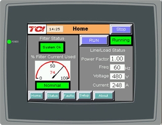
HMI Display
Fully featured 65k color touchscreen HMI display:
Harmonics and Power Quality
Variable frequency drives and other types of non-linear loads take the incoming power from the utility and modify it for more efficient use within a wide range of applications. The conversion process creates current and voltage distortion.
If non-linear loads represent a significant portion of the entire installed load, this distortion begins to cause problems throughout the electrical system:
- Transformer and distribution equipment overheating
- Random breaker tripping
- Sensitive equipment may fail completely
- Poor power factor
Performance
Unfiltered waveform with Injection
Current from the HGA
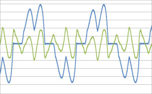
Resulting Line Current
Waveform with HGA
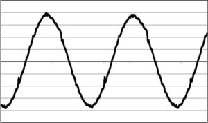
- By actively monitoring the line or load current, the HGA harmonic filter determines the nature and quantity of harmonic currents in the system and cancels the same by injecting equal amounts of harmonic currents opposite in phase. A state-of-the-art high speed DSP controller and a pulse width modulated (PWM) IGBT based power converter help to provide virtual real time compensation of non-linear load demanded by VFDs and other applications. HGA also inherently tries to synchronize the line current with its voltage resulting in near unity displacement power factor. Thus, HGA provides solutions for both reactive current and harmonic current compensation.
Meeting IEEE-519 Recommendations on Harmonics
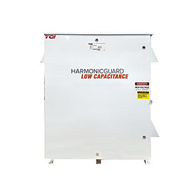
The HGA active harmonic filter provides a cost effective, efficient solution allowing the user to meet IEEE-519 requirements. Using harmonic analysis software, TCI can help customers meet IEEE-519. Typical applications include:
- Wastewater treatment plants
- Commercial buildings
- Hospitals
HGA Filters Versus Other Harmonic Solutions
The HGA active filter can be a better overall system solution when compared to large, expensive 18 pulse VFDs or multiple passive drive-applied filtering:
- Save money
- Save space
- Reduce energy losses
Bus-Applied Configuration for MCC or Switchboard
This bus-applied filter design can be directly connected to the power bus in standard MCC and Switchboard configurations. As with other bus-applied designs, impedance must be installed on the load side of the HGA filter.
Product Specifications
- TDD Reduction to 5% or better at Full Load
- Power Factor Correction to less than or equal to .98 lagging
- Power Factor Improved to near Unity
- Response time of less than 8 ms to step load changes
- Additional filters can be added to increase correction capability
- Units can be paralleled without any calibration
- Self-Commissioning Installation
- Modular design
- Harmonic Cancellation to the 50th harmonic
The HGA active harmonic filter is a very sophisticated, stable, and effective solution for harmonic and reactive power compensation.
IEEE Standard 519-2014
Table 2 – Current distortion limits for systems rated 120 V through 69 kV
| Maximum harmonic current distortion in percent of IL | ||||||
| Individual harmonic order (odd harmonics) a, b | ||||||
| ISC/IL | 3≤h<11 | 11≤h<17 | 17≤h<23 | 23≤h<35 | 35≤h≤50 | TDD |
| <20c | 4.0 | 2.0 | 1.5 | 0.6 | 0.3 | 5.0 |
| 20<50 | 7.0 | 3.5 | 2.5 | 1.0 | 0.5 | 8.0 |
| 50<100 | 10.0 | 4.5 | 4.0 | 1.5 | 0.7 | 12.0 |
| 100<1000 | 12.0 | 5.5 | 5.0 | 2.0 | 1.0 | 15.0 |
| >1000 | 15.0 | 7.0 | 6.0 | 2.5 | 1.4 | 20.0 |
a Even harmonics are limited to 25% of the odd harmonic limits above.
b Current distortions that result in a dc offset, e.g., half-wave converters, are not allowed.
c All power generation equipment is limited to these values of current distortion, regardless of actual ISC/IL.
where
ISC = maximum short-circuit current at PCC
IL = maximum demand load current (fundamental frequency component) at the PCC under normal load operating conditions.
Manuals: Current and Legacy
The table below includes links to current and legacy active filter manuals. The software version of the filter is noted on the About screen, on the HMI display.
Manuals
| IOM Manual English | HMI version on About screen |
| Version K | Current-HMI Rev K |
| Version J | HMI Rev K |
| Version H | HMI Rev K |
| Version F | HMI Rev J |
| Version E | HMI Rev I |
| Version B | HMI Rev D – Rev H |
Quick Start
| Quick Start English | Quick Start Español | Quick Start Français | HMI version on About screen |
| Version C | HMI Rev K | ||
| Version B | Version B | Version B | HMI Rev I |
| Version A | Version A | Version A | HMI Rev D – Rev H |
