$0.00
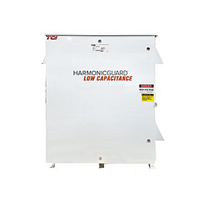
Our HarmonicGuard Low Capacitance filter (HGL) adds to our line of options for passive filters. The HGL was designed to be compatible with 5%THD performance.
The introduction of the HGL addresses concerns of excess capacitance in generators
- Haz clic para compartir en Facebook (Se abre en una ventana nueva)
- Haz clic para compartir en Twitter (Se abre en una ventana nueva)
- Haz clic para compartir en Pinterest (Se abre en una ventana nueva)
- Haz clic para compartir en Tumblr (Se abre en una ventana nueva)
- Haz clic para compartir en Google+ (Se abre en una ventana nueva)
 Our HarmonicGuard Low Capacitance filter (HGL) adds to our line of options for passive filters. The HGL was designed to be compatible with 5%THD performance.
The introduction of the HGL addresses concerns of excess capacitance in generators. Excess capacitance can cause problems such as:
- Causing leading Power Factor
- Creating over-excitation in a generator
- Controling both power factor and harmonics together
The Low Capacitance filter reduces the amount of reactive power and enables lower power, lower cost generators to be used.
The HGL filter is built using the same highest quality components as the HGP filter with the same available options.
The HGL will offer:
- Options for open chassis, Type 1 and Type 3R enclosures
- Contactor – Can be used to disconnect the tuning circuit.
- Vibration Pads – Reduces audible noise.
- Floor Stand – 12” steel feet for Type 3R enclosures 125HP and below. Units 150HP and above include provisions for floor mounting.
- Oilfield Duty – features components designed specifically for oil and gas field applications to handle the additional electrical stress. Designed for cyclical loads these units will be available in Type 3R enclosures and will be for use with HP ranges from 40 to 200HP.
- True 100kA SCCR
Limits Harmonic Distortion
- As low as a 1:1 Generator:HGL power rating
- Performance of 5% or lower THD at full load with Isc/IL<20
- Meets IEEE-519 requirements
Performance
Before HGL
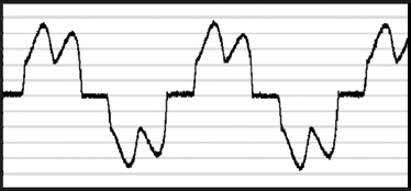
After HGL
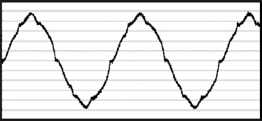
The HGL not only limits current distortion to less than 5% TDD, it also improves true power factor. Multiple package options will allow TCI customers to choose the right filter configuration for the application. Since every power system is different, harmonic mitigation requirements will differ, and even IEEE limits change based on the system loading characteristics. The HGL product returns the power of choice to the customer, allowing for different configurations to achieve different performance and monitoring results.
Minimum System Requirements
The guaranteed performance levels of this filter will be achieved when the following system conditions are met:
- Frequency: 60Hz ± 0.75Hz
- System Voltage: Nominal System Voltage (line to line) ±10%
- Balanced Line Voltage: Within 0.5%
- Background Voltage Distortion: < 0.5% THVD
Using the input current as the base, the input current waveform shall be consistent with that of a VFD with 5% AC line reactance at full load and Isc/IL<20.
Note: The presence of background voltage distortion will cause motors & other linear loads to draw harmonic currents. Additional harmonic currents may flow into the HGL filter if there is harmonic voltage distortion already on the system.
IEEE Standard 519-2014
Table 2 – Current distortion limits for systems rated 120 V through 69 kV
| Maximum harmonic current distortion in percent of IL | ||||||
| Individual harmonic order (odd harmonics) a, b | ||||||
| ISC/IL | 3≤h<11 | 11≤h<17 | 17≤h<23 | 23≤h<35 | 35≤h≤50 | TDD |
| <20c | 4.0 | 2.0 | 1.5 | 0.6 | 0.3 | 5.0 |
| 20<50 | 7.0 | 3.5 | 2.5 | 1.0 | 0.5 | 8.0 |
| 50<100 | 10.0 | 4.5 | 4.0 | 1.5 | 0.7 | 12.0 |
| 100<1000 | 12.0 | 5.5 | 5.0 | 2.0 | 1.0 | 15.0 |
| >1000 | 15.0 | 7.0 | 6.0 | 2.5 | 1.4 | 20.0 |
aEven harmonics are limited to 25% of the odd harmonic limits above.
bCurrent distortions that result in a dc offset, e.g., half-wave converters, are not allowed.
cAll power generation equipment is limited to these values of current distortion, regardless of actual ISC/IL.
where
ISC = maximum short-circuit current at PCC
IL = maximum demand load current (fundamental frequency component) at the PCC under normal load operating conditions
